Abstract
Original text · supplied arXiv v1 manuscript (22 September 2026)
Inter-satellite optical links demand high-precision fine tracking while preserving sufficient received power for data communication, yet these functions are often treated separately at the receiver. This paper proposes a dual-function optical receiver that integrates data reception and fine tracking on a shared, intentionally defocused receiver plane. The architecture combines a central data lens with an annular four-segment tracking detector, creating a fundamental tradeoff between data-power collection and angular-estimation capability. A scalar Fresnel wave-optical model is developed together with nonlinear two-dimensional calibration and a noise-aware worst-case angular-accuracy framework. The receiver geometry is then jointly optimized to maximize the guaranteed fine-tracking range subject to a minimum data-power constraint. Results demonstrate that appropriate co-design of the central aperture and defocus substantially enlarges the usable fine-tracking region while maintaining the required communication-path power. The proposed framework provides a receiver-level benchmark for analyzing and designing integrated communication-and-tracking architectures in future optical inter-satellite terminals.
ENGINEERING QUESTION
Can one compact optical receiver recover data and keep a satellite laser beam aligned?
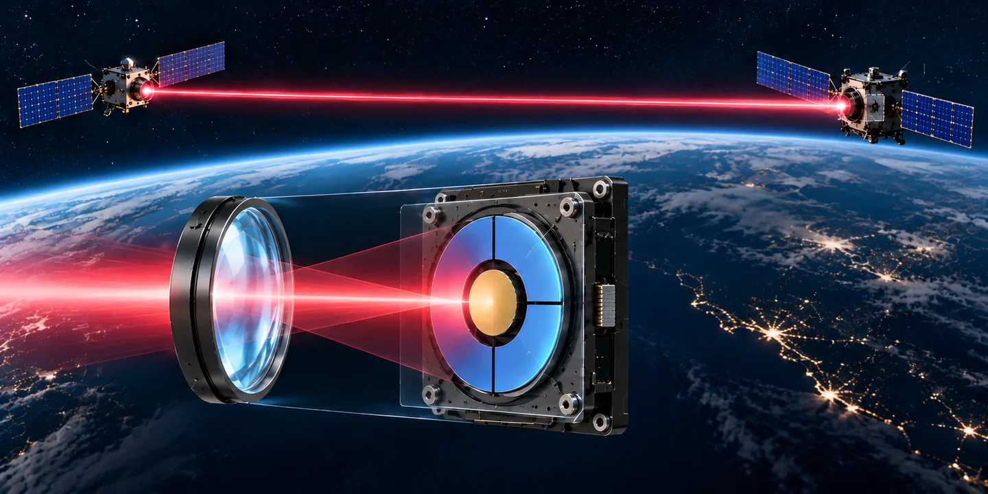
The proposed receiver combines a central data-collection lens with a surrounding four-segment tracker on one intentionally defocused plane, removing the conventional receiver-side data/tracking beam-splitter branches. At −40 dBm incident power, the numerical design retains 25.60% of receiver-plane power for the central data path and supports a 0.65 mrad fine-tracking radius under a 10 µrad angular-error requirement. Compactness is an architectural motivation; the paper does not report a measured terminal mass or package-volume reduction.
Share a receiver plane for data and tracking
A primary receiver lens directs the incoming field onto a plane placed slightly before its nominal focus. A central circular data lens collects communication-path power, while four annular tracking segments surround it. A radial guard gap separates the central lens from the tracker, and a cross-shaped inactive gap separates the four segments.
The architecture integrates the two functions without conventional receiver-side beam-splitter branches. A larger central lens captures more data power but reduces the active tracking annulus. Intentional defocus spreads the optical field across the plane, changing both tracking sensitivity and central collection. The design therefore treats communication power and fine tracking as coupled optical requirements.
Manuscript · Sections I–II; Fig. 1; Eqs. (1)–(6)
Calibrate the full two-dimensional response
A scalar paraxial Fresnel model propagates a tilted, locally planar input wavefront through the primary lens. Optical power is integrated over the central data aperture, active tracking segments, inactive gaps and space outside the receiver, preserving the modeled power balance.
Normalized differences of the four tracking-segment powers provide horizontal and vertical tracking signals. A sampled two-dimensional forward map and interpolated nonlinear inverse estimate the residual angle of arrival. The method retains cross-axis coupling and restricts calibration to unique, locally invertible, nonfolding response regions. Numerical interpolation error is evaluated separately from detector-noise error.
Manuscript · Sections II–III; Eqs. (6)–(9)
Design for the least favorable pointing direction
The tracking-channel noise model includes signal, background and dark-current shot noise together with input-referred thermal-current noise. Each noisy normalized measurement passes through the nonlinear inverse calibration. Accuracy is measured as the radial two-axis angular RMSE, rather than one component or one favorable angular cut.
The usable tracking radius is the largest continuous centered angular disk for which the worst azimuthal RMSE stays within 10 µrad at every smaller radius and the calibration remains valid. It is not the full geometric field of view or the entire angle sweep used to characterize the receiver.
The central-lens diameter and defocus are jointly optimized at −40 dBm incident power. The central path must collect at least 25% of receiver-plane optical power at zero residual angle. This on-axis constraint does not guarantee the same data-power fraction at every off-axis point in the tracking disk.
Manuscript · Sections IV–V; Eqs. (10)–(19)
Numerical geometry and operating conditions
The simulations use 1550 nm light, a 60 mm-diameter primary lens with an 80 mm focal length, and a 1 mm-diameter tracking annulus. The radial guard gap is 20 µm and the cross-shaped gap is 30 µm; primary-lens transmission is 0.95. Tracking detectors have 0.9 A/W responsivity, 1 nA dark current, 0.5 nA background current, 1 pA/√Hz input-referred current-noise density and 20 kHz noise bandwidth.
The selected central-lens diameter is 170 µm and defocus is 0.450 mm, placing the shared receiver plane at 79.550 mm behind the primary lens. At −40 dBm (100 nW) incident power, the central data-power fraction is 25.5951%, on-axis angular RMSE is 9.176 µrad, and full-chain verification gives a 0.650 mrad continuous worst-case tracking radius. The coarser discrete optimization search gives 0.610 mrad; these are distinct evaluations of the selected geometry.
With the same geometry, the reported tracking radius grows to 1.12 mrad at −35 dBm and 1.33 mrad at −30 dBm, with on-axis RMSE values of 2.91 and 0.93 µrad. At −45 dBm, the on-axis RMSE is already 28.56 µrad, so there is no usable radius meeting the 10 µrad requirement.
The calibration study also shows why wide angular coverage alone is insufficient. Representative noiseless inversion errors increase from 0.048 µrad near the center to 32.0 and 290.9 µrad at larger offsets as the normalized response approaches saturation and loses local sensitivity.
Manuscript · Sections V–VI; Figs. 2–4
What compact integration establishes
The contribution is an integrated receiver architecture and a receiver-level co-design benchmark. Sharing a plane and avoiding separate beam-splitter branches can simplify the optical arrangement, but a realized terminal still needs mechanical packaging, detector electronics, calibration and steering control. The paper does not quantify a hardware mass or volume saving.
The analysis starts after coarse acquisition. Transmitter-to-receiver propagation and coarse-pointing dynamics are excluded, and the input is specified by incident receiver power and residual angle of arrival. The study uses an ideal thin primary lens, uniform pupil illumination, scalar paraxial propagation and equivalent Gaussian current noise. It establishes numerical angular accuracy and power collection, rather than a built receiver, an on-orbit demonstration or a measured data-rate improvement.
Manuscript · Sections II and VII
Publication record
- Authors
- Meysam Ghanbari, Mohammad Taghi Dabiri, Akram Alomainy, Qammer H. Abbasi, Mazen O. Hasna, Khalid A. Qaraqe
- Venue
- 2027 IEEE Vehicular Technology Conference (VTC2027-Spring)
- Location
- Hamburg, Germany
- Status
- Submitted
- Year
- 2027
The abstract, full author order, optical model and numerical results follow the supplied arXiv:2609.25971v1 manuscript dated 22 September 2026. Meysam Ghanbari has confirmed that he will present the work at IEEE VTC 2027-Spring in Hamburg, 20–23 June 2027. The existing Submitted manuscript status is retained; an individual session slot, proceedings record and DOI are not yet recorded. The technical explanation is editorial and separate from the original abstract. Research note updated 2026-10-10.